Case study: Five Shades of Upgrades
Cable system upgrades – mainly exploiting improvements in the terminal transmission technology – have provided significant capacity increases and extended the useful life of a number of systems.
This case study will review where we are now and speculate on what the future could offer. Most of the focus will be on increasing capacity simply by changing the terminal equipment, but the question of whether it is practical and worthwhile to consider wet-plant upgrades will also be addressed.

Dry-plant upgrades
In the last ten years, optical transmission has experienced dramatic improvements driven mainly by the move to coherent systems where traffic is carried on orthogonal polarisations. Digital Signal Processing (DSP) there are more technology varients than shown completely compensates for both chromatic and polarisation-mode dispersion and removes the need for a number of optical components.
At the same time, Forward Error Correction (FEC) has benefited from the use of soft-decision decoding, which has increased the coding gain over that possible with hard decisions. The combination means that today’s optical budgets have a lot of extra dBs compared with earlier systems which used On/Off Keying (OOK), simpler FEC schemes and only one polarisation.
The result is that we are now able to operate systems originally designed for 10G per wavelength at 100G per wavelength, and some system upgrades
have achieved capacity increases of significantly more than ten times the original design capacity. The performance increase that is possible depends on what generation of system is being upgraded and the following diagram illustrates a few of steps in the last few years, although the numbers are not precise, as there is some variation between suppliers the result.
A key point is that the performance improvement that is possible depends on where one starts. The capacity increase for an early system is potentially quite large, while upgrading a fairly recent system will add a smaller performance difference and thus relatively less capacity. Looking at the figure, one also sees a hint that progress is slowing, as we are starting to approach fundamental limits. Nonetheless, there is still progress.
The latest modules use digital pulse-shaping to create almost Nyquist-shaped pulses, which allow the wavelengths to be spaced closer than before and to approach one of the fundamental limits. In effect, Nyquist’s law requires an optical bandwidth equal to the symbol rate or greater, but the symbols are not limited to ones and zeros, and the move to coherent DSP was accompanied by a move away from binary modulations. Quadrature Phase Shift Keying (QPSK) uses transmitted symbols that consist of one of four possible phase states, i.e., two bits of information. The next generation of modules offered additionally 8QAM and 16 QAM, where each symbol can encode three and four bits respectively, giving the potential for even greater capacity per wavelength. The arrangement of possible phase and amplitude states is known as a “constellation” and the following diagram shows QPSK, 8QAM and 16QAM.
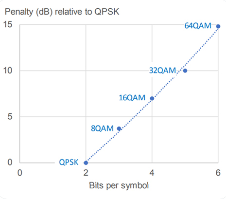
These latest modules process two wavelengths, with QPSK, 8QAM and 16QAM offering 200G, 300G and 400G respectively. The extra capacity, however, comes at a price. The greater the number of points in a constellation, the greater the Optical Signal to Noise ratio (OSNR) needed to achieve a given error performance. The graph to the right shows how this increases.

Going from QPSK to 16QAM doubles the capacity per wavelength, but it requires at least 7 dB extra OSNR, which may not be available on the system to be upgraded. If not, one would consider 8QAM, which needs around 4 dB more, but if there were only 3 dB of margin available, one would be limited to QPSK. Fortunately, the next generation of chips is offering a variety of more complicated modulations that effectively create schemes which fit between those shown on the graph and allow a granularity of less than 100G per dual-wavelength. Bit Interleaved Coded Modulation and variants are one option, but there are other refinements, such as Probabilistic Constellation Shaping, where high power points in the constellation are transmitted less frequently than low power points, thus reducing non-linear penalties and improving the overall performance, albeit by relatively small amounts. Another approach is Geometric Constellation Shaping, where the constellation is no longer a rectangular grid, but is distorted to improve the performance.
Refinement, rather than revolution, is the case for FEC, where it is becoming increasingly difficult to make significant improvements. Increasing the code overhead does provide better correction, but it also increases the symbol rate (and thus the required bandwidth), and most suppliers seems to have opted to make only minor increases, resulting in relatively small improvements in net coding gain.
Processing at the receiver to mitigate the effects of non-linearity has for a long time been a hot topic at conferences and one might speculate that the ever-increasing complexity of available DSP chips must make this more practical. However, non-linearity mitigation involves a huge amount of computation and current practical implementations seem to add little benefit – it will be interesting to see if this changes in the future.
There are, however, other uses for the increased processing power. Highly secure traffic encryption is offered by some of the latest designs, which are also starting to offer features aimed at simplifying access to lower orders of traffic. While these don’t have a direct impact on performance, they do offer the potential for more compact and cost-effective circuit packs.

Wet-plant upgrades
So far, almost all upgrades have been essentially to the terminal equipment, in some cases at the same time as recovering and relaying part of a cable system. While in general this remains the most cost-effective and quick solution, it’s worth considering upgrades of the subsea plant. Of these, the most obvious is to keep the shore-ends and replace the cable and repeaters, or just the cable in the case of a repeaterless system. Keeping the shore-ends removes significant installation cost and usually simplifies the permitting process, although it could be considered as more like building a new cable system than a true upgrade. The only downside is that the old system must be cut before the new system can be implemented.
A more ambitious idea is to retain the cable and replace only the repeaters, thus improving both the bandwidth and the OSNR. Clearly the potential benefit is the saving on the cable and the simplified permitting. Repeater replacement, however, is not a trivial task. Except in quite shallow water, it isn’t really practical simply to cut out and replace a repeater; attempting such an operation in deep water could take some time grappling for the cable and would add a significant amount of slack cable, which is undesirable for a number of reasons. In general, a better approach would be to recover the cable and repeaters, replace all the repeaters with new ones and then re-lay the system. This solution also has the benefit of allowing the new repeaters to be spaced optimally, rather than being positioned at the points where the old system had them. However, it requires two marine operations and is likely to be cost-effective only if the majority of the cable and repeaters are not buried. Determining if it is cost-effective requires an assessment of the marine costs and comparing them with the alternative of sourcing new cable, transporting it and then having a single marine operation.
It’s important, however, not to dismiss changes in wet-plant, as upgrades such as that of HUGO, where the addition of two repeaters added significant potential capacity and operation margin. One can also envisage an unrepeatered system where the addition of two ROPAs (Remote Optically Pumped Amplifiers) could add the 7 dB performance needed to move from QPSK to 16QAM and thus double the system capacity. Another possibility is the insertion of a branching unit to allow traffic to land in a new location; as before, the marine aspects will not be trivial and will depend on water depth. A further complication for a third-party upgrade will be to ensure electrical compatibility between the existing cable systems and the new branch and cable, assuming that the branch needs to be powered.
It’s clear that wet-plant upgrades involve significant cost and disruption, and in any event, are likely to be accompanied by changes to the dry plant, which can be carried out with much less traffic disturbance.
Summary
The simple fact that terminal developments have added huge performance and capacity gains means that we must now be closer to the fundamental limit set by Shannon’s law. This, combined with the increasing need to upgrade more recent systems, which start from a higher level of technological sophistication, would suggest that capacity increases will not be as great as they were in the past. Of course, technical progress will continue and we are likely to see some refinements in terms of the modulation schemes used and some modest improvements in performance from this and better FEC. It’s also likely that terminal development will focus on other aspects of circuit pack performance, including features such as security, reduced power consumption, smaller size and the need to support Open Systems.he worked in Alcatel Submarine Networks’ Technical Sales before moving to head Product Marketing.

Written by Tony Frisch
Tony Frisch joined Xtera in 2004 initially managing Marketing and Proposals for terminal equipment and upgrades and then responsible for products such as Repeaters and Branching Units, and now serves as CTO. Tony started work at BT’s Research labs investigating cable problems and then moved to Alcatel Australia, becoming involved in testing and commissioning submarine systems. A move to Bell Labs gave him experience in terminal design and troubleshooting, after which he went back to Alcatel France, where he worked in Alcatel Submarine Networks’ Technical Sales before moving to head Product Marketing.
